Note
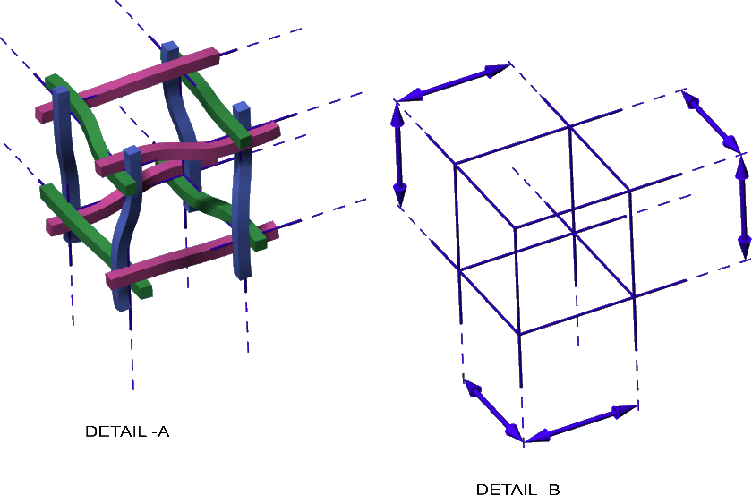
Detail -A
shows a small cut-out of a 3D-weavement.
Also shown in blue:
the cubic 3d-grid structure that
locates the elements constituting the weavement.
Detail -B
shows the grid structure by itself.
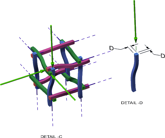
detail -C
shows the constituent elements cut back to
reveal their typical square cross-section,
indicated by the green arrows.
Detail -D
shows such a cross-section
& it’s dimension, being D X D.
All dimensions of the weavement are
defined in terms of “D”.
The typical spacing -the “pitch”- of the
3D-grid structure is shown in Detail -B;
designated by the blue arrows.
Incase of the weavement cut-out shown in Detail -A
the pitch is 10-D.
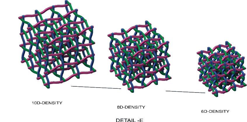
The “D-number” of the weavement
then is a measure of it’s openness or density.
Detail -E shows a series of weavements
having the following densities:
10D, 8D, 6D.
All the weavements shown
elsewhere in this site
have a density of 6D.
—————————————–
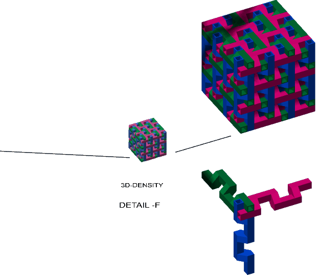
The maximum density that
the weavements can have is
3D.
At that density
the curvatures of the constituent elements
will have become 90° angles.
See Detail -F.
When 3D-printed in a larger “industrial” size
with constituent elements that are
hollow & open ended
in the manner of square tubing
-as shown in the enlarged view-
an item emerges with
possible novel usages.