NOTE -1
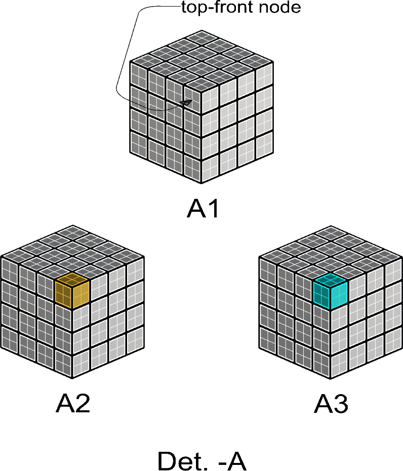
In Det. -A
(3) weavements are shown,
designated by A1, A2, A3 respectively.
A1 has
the “top-front node” is pointed out.
A2 & A3 have
a left-handed- & a right-handed top-front node
respectively.
NOTE -2
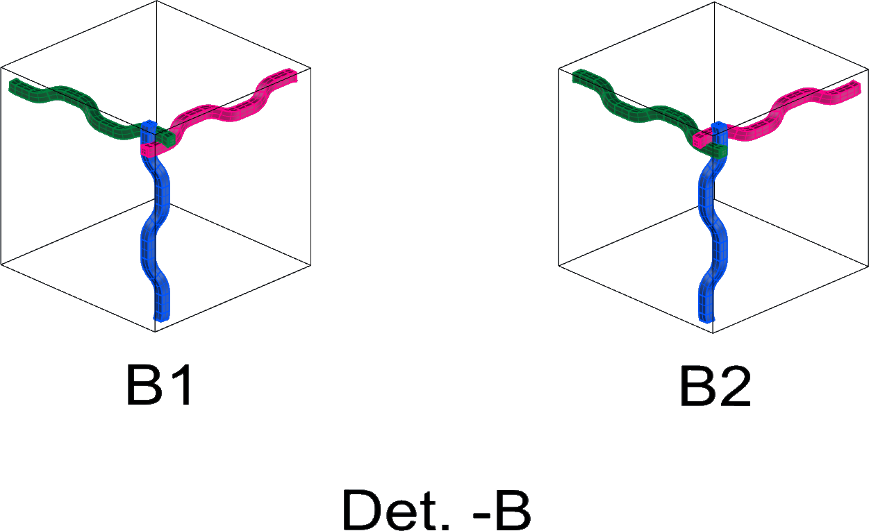
In Det. -B
B1 & B2 show the elements constituting
the left-hand node & the right-hand node
respectively.
These can be called the “top-front elements”.
For illustrative purposes
the best orientation of the top-front elements
is as shown in B1 & B2
because so oriented
the weavement-type can be recognized most easily.
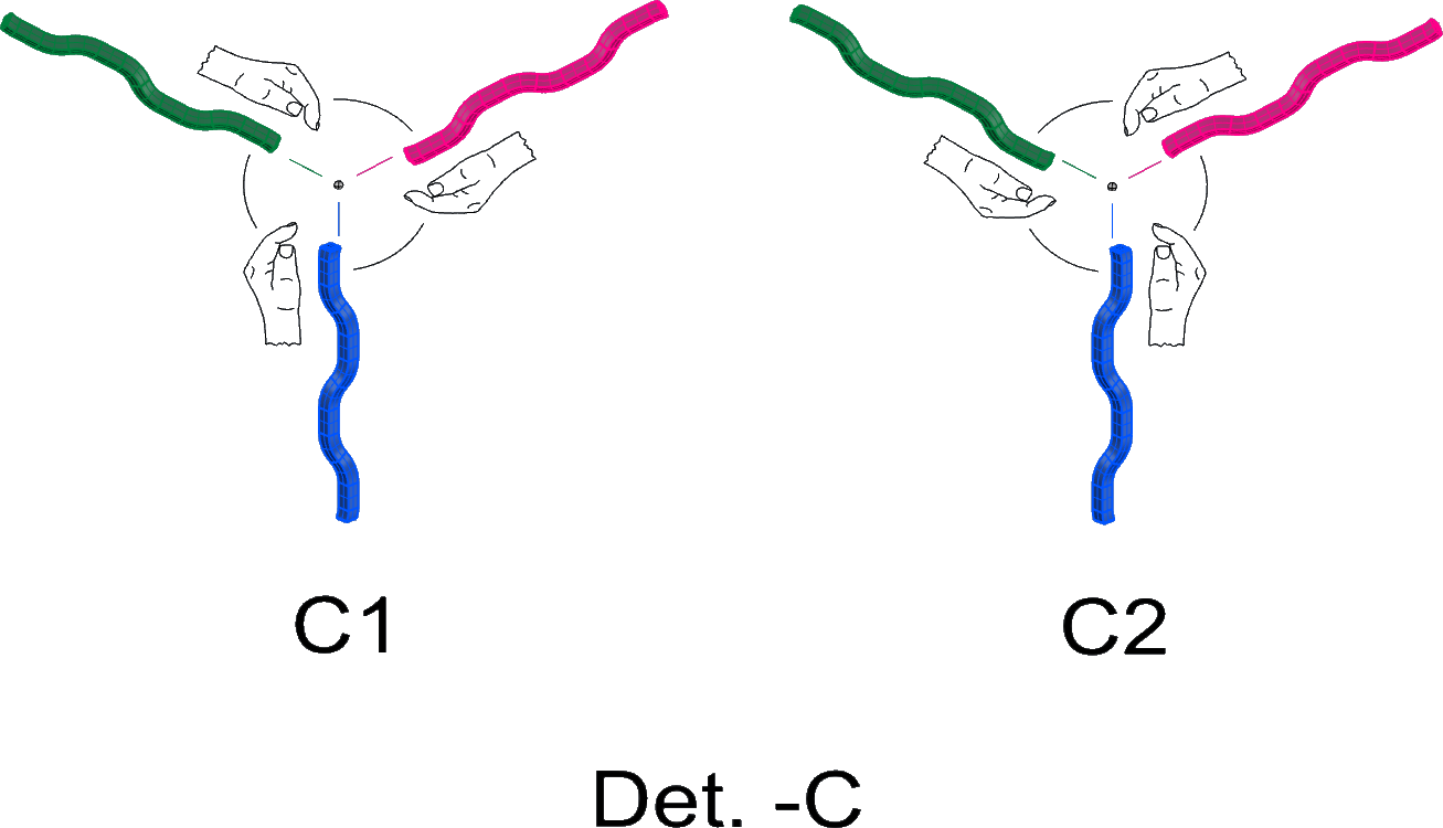
NOTE -3
In Det. -C
the elements constituting the
left-handed top-front node in B1 can be seen to have
curvatures at their ends that are left-handed in orientation,
the elements constituting the
right-handed top-front node in B2 can be seen to have
curvatures at their ends that are right-handed in orientation.
These orientations are left- or right-handed
according as they match
the curvature of one’s left-or right-hand respectively,
as shown pictorially in C1 & C2 respectively.
NOTE -4
————
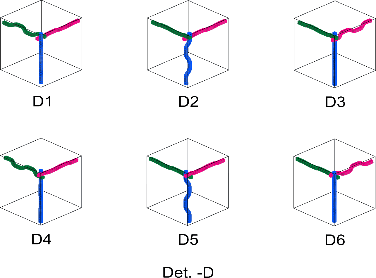
In Det. -D
D1 thru D6 show examples of top-front elements
that are undesirable because they diverge from
the ‘best orientation’ practice proposed in
Det. -B & Det. -C.